How to Code Continuous Servo Arduino
360 degree servo motors (also known as continuous rotation servo motors) are a special version of servo motors that can rotate continuously.
Unlike their universal counterparts, which can only rotate from 0° to 180° and have no speed control other than position control, continuous rotation servos allow us to control the rotational direction and set the speed as well.
Continuous rotation servos are found in many applications such as small hobby robots like the BoeBot.
In this tutorial, I will show you what 360 degree servos are, how they work and how to control one using an Arduino Uno.
First, I will explain how the continuous rotation servo works and how to connect one with the Arduino.
Then, I will show you how you can create a circuit to control the speed and the direction of a servo motor.
Supplies
To follow the steps in this tutorial, you will need the following items:
Hardware Components
| FEETECH FS90R 360 Degree Continuous Rotation Micro Servo Motor | x1 |
| Arduino UNO R3 | x1 |
| Male-to-Male Jumper Wires | x1 |
| Breadboard | x1 |
| 10 kΩ potentiometer (breadboard type) | x1 |
| USB cable type A/B | x1 |
| 5V power supply (optional) | x1 |
Software
Makerguides.com is a participant in the Amazon Services LLC Associates Program, an affiliate advertising program designed to provide a means for sites to earn advertising fees by advertising and linking to products on Amazon.com.
You might already be familiar with the servo motors, and think that 'I already have one'.
But look close where the item description mentions '360 degree servo' or 'continuous rotation servo'.
For FEETECH motors, they specifically mention the phrase 'continuous rotation servo' on the sticker found on the motor housing.
So, if you're purchasing the motors from someone else other than the link mentioned above, please confirm that they are in fact 360 servos before purchasing!
->Read our article about How Easy Is It To Learn Arduino?
Continuous Rotation Servo Motors vs. Universal Servo Motors
Continuous rotation servos are a specialized version of universal hobby servo motors.
Universal hobby servos consist of three major sections:
1. Electric motor
This is typically a regular brushed DC motor that operates on 5V-12V depending on the supply.
2. Gear System
If you have used a servo motor before, you might have observed that a servo motor turns much slower than a regular motor, but it is very hard to stop its rotation by hand.
This is because of a gear system that increases the torque of the motor output, which in turn reduces the rotational speed.
3. Feedback and Control Circuitry
The control circuitry consists of a feedback mechanism, typically a potentiometer connected to the output shaft of the gearbox to find out what is the current position of the gear motor.
Depending on the current position and the signal we give it to rotate to a different position, the control circuit gives power to the motor to reach the desired position.
Servo motors also have 'holding torque'. This means that when we direct a servo motor to a certain position and try to rotate the shaft by hand/external force, it will counteract our effort and try to maintain its position.
[Be careful when you try this; if your servo is a plastic geared one, you could accidentally damage its gears!]
If you want more in-depth information on universal servo motors, feel free to check out our How to control servo motors with Arduino tutorial!
What makes a continuous servo motor special?
A typical servo motor needs a ~50Hz PWM signal that has pulse widths ranging from 1ms to 2ms to control the position of its shaft.
For example, if our pulse width is 1.5ms, the motor will instantly rotate to its 90 degree position and maintain the angle until we change the pulse width.
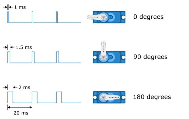
According to some manufacturers, their pulse widths/frequencies can slightly change by 0.5ms to 2.5ms and most of the RC hobby servos can accept pulse frequencies in the range of 40-200Hz.
Continuous servos, on the other hand, do not provide position control. For example, if we provide a 1.5ms pulse at 50Hz, the servo will not rotate.
If we decrease the pulse width from 1.5ms, the motor will start to rotate in the clockwise direction. If we increase the pulse width, it will rotate in the counterclockwise direction.
If the pulse width is much higher or lower than 1.5ms (for example, 1.8ms or 1.2ms), the motor speed will increase.
At 2ms, the motor will have its maximum counterclockwise speed and at 1ms, the motor will turn at its maximum speed in the clockwise direction.
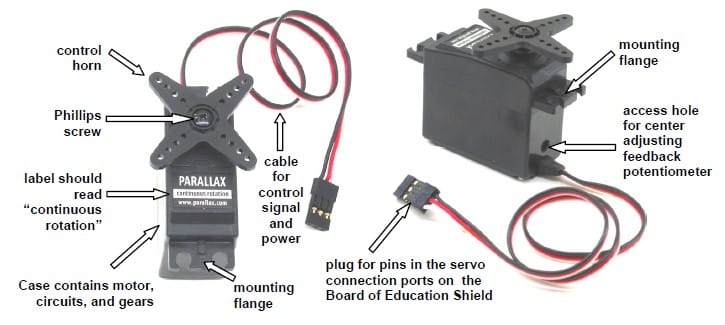
It is worth noting that continuous servos do not offer exact position control of the shaft.
We can only control the direction and the speed of rotation.
In universal 180 degree servos, we can control the position and the direction but not the speed.
Continuous servo motor pinout
The pinout for the 360 degree servo is the same as the universal, 180 degree servo motor.
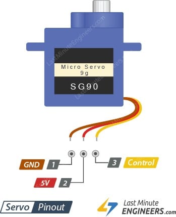
The brown and red pins are the power pins, and the yellow pin is the signal input pin.
For special cases such as the Adafruit Feedback 360 Degree servo motor, there is an additional pin which outputs 0-5V voltage depending on the 0-360 degrees angle of the shaft.
If you have one of those, you can identify the exact position of the shaft at any given moment by measuring the analodRead() value of that pin.
How to use a 360 degree servo with Arduino
Let's first start with the Arduino software installation and testing the development board.
Step 1: Arduino IDE installation
If you haven't already installed the Arduino IDE on your system, please follow this tutorial by thecoderworld to install it on your system.
Step 2: Installing necessary libraries
For this tutorial, we do not need to install any libraries. The Arduino IDE comes with everything we need out-of-the-box.
Step 3: Wiring the 360 degree servo motor with Arduino Uno
The three-pin connector of the servo motor has the above mentioned pinout. If you have a small 5V servo motor like the one I listed here, you can directly connect it as shown below:
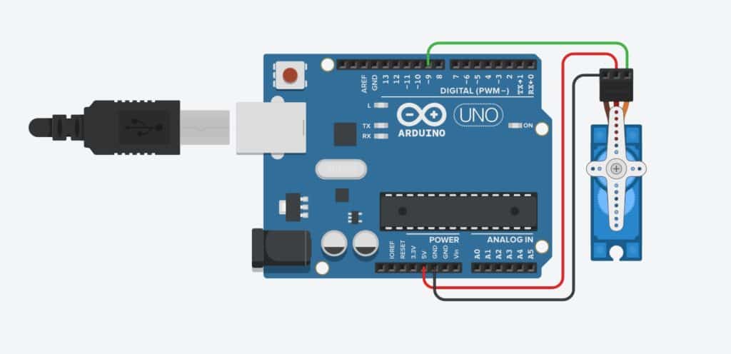
NOTE: To minimize the risk of drawing too much current and damaging your USB port, do not put heavy loads on the motor. If you need the motor to control the position of something, please connect an external 5V (or a supply that can provide the operating voltage of the motor) supply as shown in the diagram below.
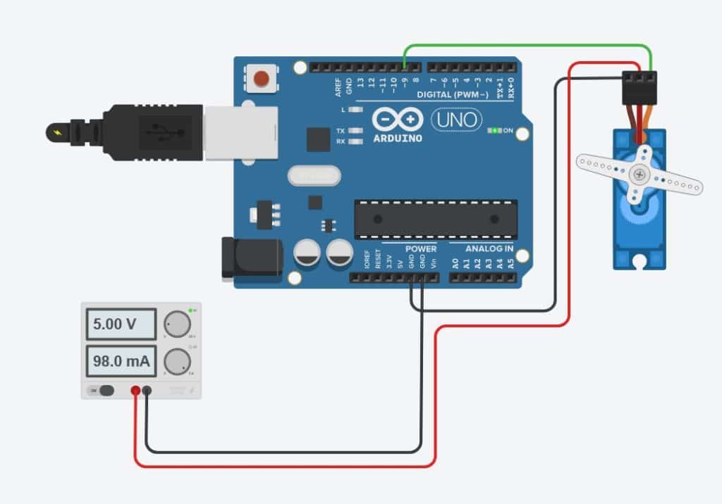
After connecting everything, plug the Arduino to your computer using the USB cable.
Step 4: Setting up the Arduino for uploading the code
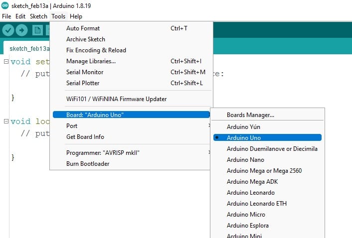
Go to Tools -> Board menu and select Arduino Uno from the list. Then, go to Tools -> Port and select the COM port.
Usually, there is only one COM port and if your Arduino is a genuine board, the IDE will most likely automatically select the port for you.
Step 5: Sample code for testing the servo
Now that we have everything set-up, let's write some code!
Like I mentioned before, the continuous rotation servo/360 servo is a special version of universal servo that allows us to control not the position, but the speed and the direction of the rotation of the motor.
The code is identical to the universal servo driving code, but the output is different.
// Include the library #include <Servo.h> // Create the servo object Servo myservo; // Setup section to run once void setup() { myservo.attach(9); // attach the servo to our servo object myservo.write(90); } // Loop to keep the motor turning! void loop() { myservo.write(45); // rotate the motor counterclockwise delay(5000); // keep rotating for 5 seconds (5000 milliseconds) myservo.write(90); // stop the motor delay(5000); // stay stopped myservo.write(135); // rotate the motor clockwise delay(5000); // keep rotating :D } Copy this code, click Upload and watch the servo rotate on its own!
->Read our guide about What You Can Build with Adruino.
Observations
The 360 degree servo will rotate in one direction (clockwise) for 5 seconds; stay still for 5 seconds and rotate in the reverse direction for another 5 seconds.
This cycle repeats as long as the power is given.
How the 360 rotation servo code works
We start by including the Servo library provided by the Arduino. This library generates and handles the 50Hz pulse required to control the servo motor.
#include <Servo.h>
If you forget how exactly you should write this line, Going to Sketch -> Include Library allows you to select the required library and the IDE will automatically add the line for you.
Next, I have created my Servo Object. This represents my servo throughout my code and whatever changes I make to this will be reflected on the actual servo.
You can name the servo object in any name you want, but make sure you:
- Start object the name with a letter
- Do not put spaces in the object name
Servo myservo;
Let's move on to the Setup section. This part of the code of the Arduino firmware runs only once as soon as we provide power to the Arduino.
I have used this section to attach my servo motor to the servo object I just created and make sure it is stopped.
I have connected the pin 9 of the Arduino to the servo motor's signal input.
By using the myservo.attach() function, I let my code know about this so when I modify the servo object, I can see the output on that particular motor.
This is particularly useful when we have multiple servo motors.
By creating one servo object per each motor, we can easily control them individually!
void setup() { myservo.attach(9); // attach the servo to our servo object myservo.write(90); } Using the myservo.write() line on a continuous rotation servo motor, we can control the direction and the speed of rotation.
For example, a universal servo reaches the center position when we write myservo.write(90). For a continuous rotation servo, the same line stops its rotation.
Any value greater than 90 causes the servo to rotate clockwise, and determines the speed.
For instance, myservo.write(95) will make the motor start rotating very slowly while using myservo.write(180) sets the motor at full clockwise speed.
Similarly, using a value less between 0 and 90 will reverse the direction of rotation.
A value close to 0 sets the motor at full counterclockwise speed while a value like 85 will slow down the speed significantly.
In the loop section, I have written a simple code to show the sequence; turn counterclockwise at half the speed for five seconds, stop rotating for five more seconds and rotate clockwise for another seconds.
Note: The code will give a result other than the one I discussed here if you have mistakenly purchased a regular servo motor!
Control the speed of a 360 degree servo using potentiometer
Sometimes you'll want to finely control the speed of a 360 degree rotation servo motor using an Arduino.
I'll show you how to read the position from a potentiometer and control the speed of the 360 degree servo using Arduino in the following steps:
Step 1: Setup the hardware
As I discussed in the previous experiment, follow Steps 1 through 4 to set up the hardware and software environment.
In addition to those steps, connect the 10k potentiometer as shown in the diagram below:
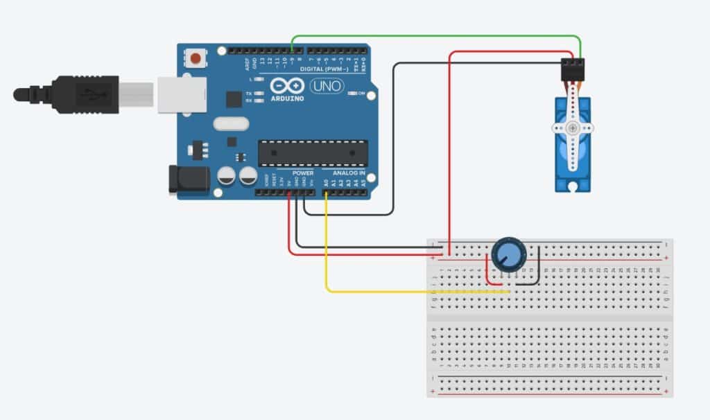
Since the potentiometer is an analog component, we need to connect it to an analog input of our Arduino. The analog pins on the arduino are marked as A0, A1 etc. I have connected the potentiometer to the A0 pin.
Step 2: Programming the Arduino to control the servo
Here's the code I wrote to control the servo motor speed and direction using the potentiometer:
#include <Servo.h> // Include the servo library Servo myservo; // create servo object to control our servo int potentiometerPin = A0; // analog pin used to connect the potentiometer int val; // variable to read the value from the analog pin void setup() { myservo.attach(9); // attaches the servo on pin 9 to the servo object } void loop() { val = analogRead(potentiometerPin); // reads the value of the potentiometer (value between 0 and 1023) val = map(val, 0, 1023, 0, 180); // scale it for use with the servo (value between 0 and 180) myservo.write(val); // sets the servo speed and direction according to the scaled value } Similar to previous code, I first started with including the Servo library and creating the servo object.
Next, I defined two variables to hold the pin name and the analog value read from the potentiometer.
int potentiometerPin = A0; // analog pin used to connect the potentiometer int val; // variable to read the value from the analog pin
In the Setup section, I attach my servo motor to the servo object I just created. As usual, this binds the physical motor to the variable myservo similar to the previous experiment.
The loop() section is where the interesting things happen!
The loop works in the following order:
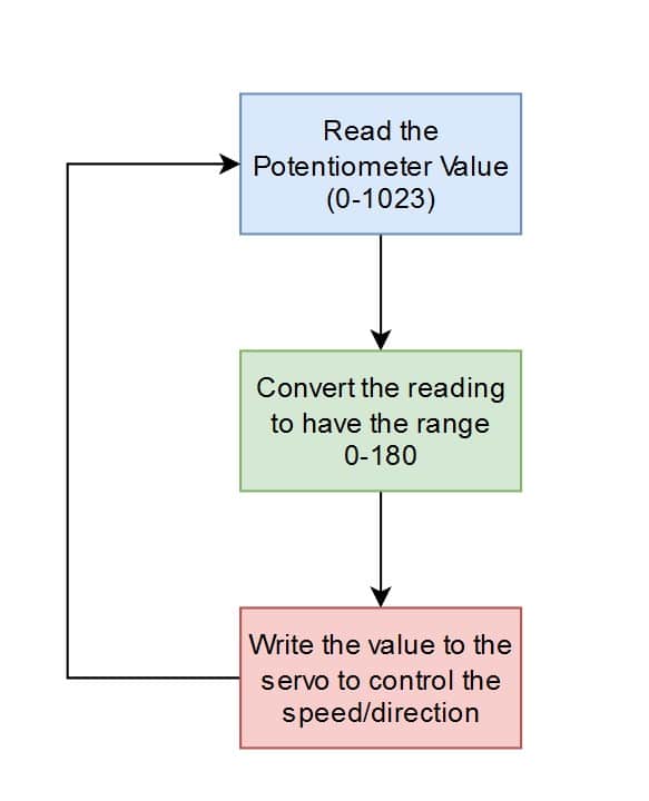
The val = analogRead(potentiometerPin); line reads the potentiometer reading, and assigns it to the variable val.
This can take any value from 0 to 1023 depending on the position of the potentiometer.
Next, I use Arduino's map() function to convert this 0-1023 value to 0-180 range because our servo expects a value between 0 and 180.
The Arduino official website has a detailed explanation of the function and its parameters.
The returned mapped value is stored in the val variable. This replaces the raw analog reading which was there before.
Lastly, I'm sending the value to the 360 degree servo by using myservo.write(val); statement to update the motor behavior.
Observations
We can observe that when the potentiometer is in the middle position, the servo motor will stop rotating.
Once you start turning the potentiometer knob clockwise, the motor will also start spinning clockwise and vice-versa.
When the potentiometer is fully rotated to either end, the servo will rotate at its maximum speed to either direction.
–> Check out our guide to the Top 12 Best Arduino Online Courses
Conclusion
In this tutorial, I have shown you how to get started with using a 360 degree servo motor with Arduino Uno.
While the 360 degree servos are somewhat uncommon in the market, they certainly have their uses in many disciplines including hobby RC projects.
This tutorial was just an introduction to the overall concept of 360 degree servos with minimal components and there is a lot we can do with these motors if used correctly.
For stable and high torque/power applications, a separate power supply is highly recommended.
Now it's time for you to get yourself a development kit, and start playing with 360 degree servos!
Do you have any questions or suggestions? Where else do you think these motors can be useful?
Let me know in the comments below!
Source: https://www.makerguides.com/how-to-control-a-360-degree-servo-motor-with-arduino/
0 Response to "How to Code Continuous Servo Arduino"
Post a Comment